

When it comes to military electronics, failure is not an option. That is why MIL-STD-461 exists to make sure electronic systems used in military environments can operate safely and reliably, even when exposed to severe electromagnetic conditions.
One of the lesser-known but critically important parts of this standard is CS116, which tests how systems handle damped sinusoidal transients – fast, repetitive disturbances that can easily throw sensitive electronics off track. In this post, we will break down what CS116 involves, what kind of equipment is required, and how to approach it in a practical, lab-ready way.
Background on MIL-STD-461 and CS116
MIL-STD-461 has been the basis of EMC compliance for U.S. Department of Defense equipment for decades. It outlines the limits, verifications, and test procedures for the control of the electromagnetic interference (EMI) and susceptibility characteristics of electronic, electrical, and electromechanical equipment and subsystems employed in military and aerospace applications.
CS116 was introduced to simulate electrical current and voltage waveforms occurring in platforms from the excitation of natural resonances. These resonances are caused by sources like:
-
- Electromechanical switching
- EMP events
- Indirect lightning strikes
- Arcing or contact bounce
- Pulse currents through system wiring
These are not hypothetical threats. CS116 is particularly relevant for equipment used in military vehicles, aircraft, space systems, and other applications where electromagnetic compatibility is critical.
What CS116 Actually Tests
CS116 falls under the “Conducted Susceptibility” category. The test applies to interconnecting cables, including power cables, and individual high-side power leads, verifying that the equipment can operate reliably even in the presence of EMI.
The signal injected is a damped sinusoidal waveform — a high-frequency sine wave that decays over time, much like the ringing you would see after an electrical impulse.
Key waveform characteristics:
-
- Frequencies tested: 10 kHz, 100 kHz, 1 MHz, 10 MHz, 30 MHz, and 100 MHz
- Pulse repetition rate: between 1 and 2 seconds
- Duration: 5 minutes
- Limit: from 0.100 amps to 10 amps, depending on frequency
The goal is to ensure that no internal resets, communication failures, or performance degradation occur when these transients are present.
Equipment You Need for CS116 Testing
The heart of any CS116 test setup is the Damped Sinusoidal Transient Generator that creates the damped sinusoidal pulses. Test equipment from EMC Partner is designed specifically for MIL-STD-461 applications.
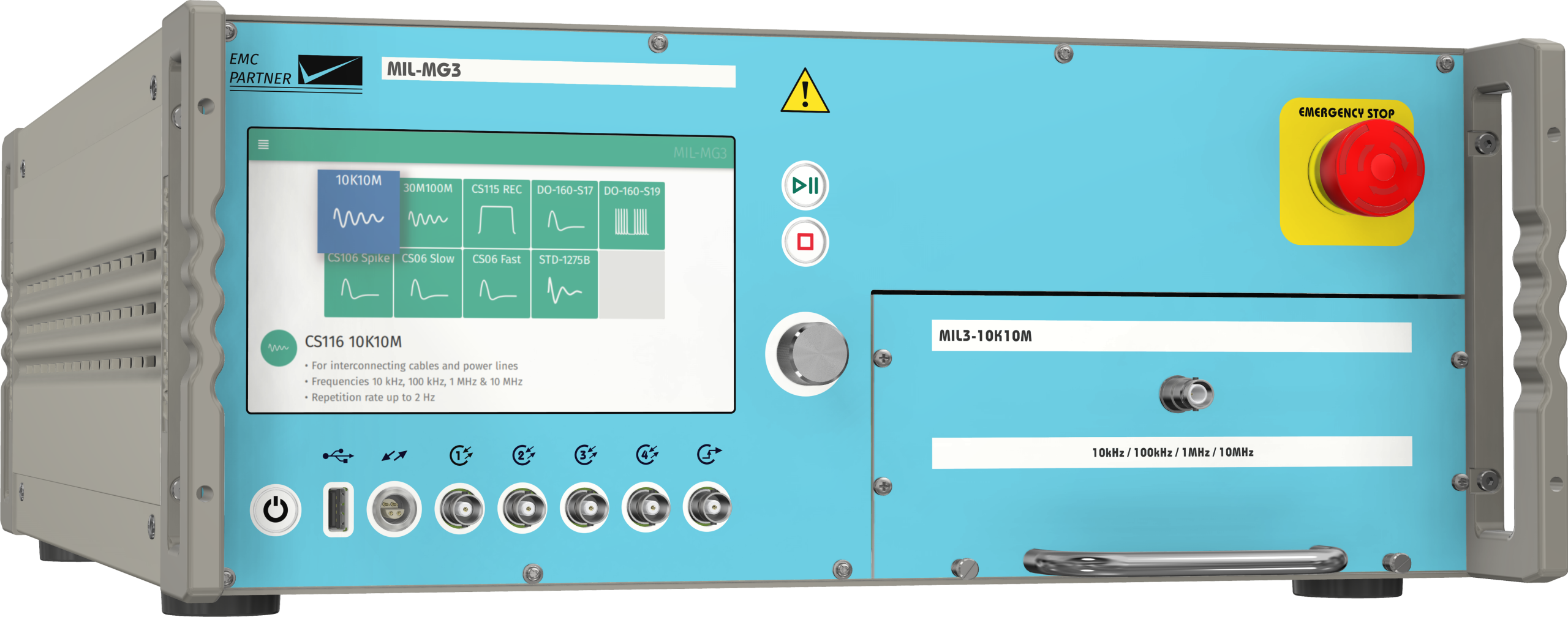
The Military Conducted Susceptibility Test Generator MIL-MG3 is a fully compliant modular test system for MIL-STD-461 CS116, CS115, CS106, CS06, and RTCA DO-160 Sections 17 and 19. It features a 7” color touchscreen with intuitive controls, solid-state switching for accurate waveforms, and a universal coupler for CS115 and all CS116 frequencies. Designed to fit even large-diameter cables.
Built on the trusted MIG2000-6 and MIL3000 platforms, it includes built-in AC power sync, electronic polarity switching, and comes turnkey with all necessary accessories and a calibration jig. The TEMA3000 software allows automated testing, sequence storage, and integrated reporting with oscilloscope waveforms.
Plugins and Accessories for MIL-MG3
-
- MIL3-10K10M: CS116. Covers damped sinusoidal transients at frequencies of 10 kHz, 100 kHz, 1 MHz, and 10 MHz.
- MIL3-30M100M: CS116. Covers damped sinusoidal transients at frequencies 30 MHz and 100 MHz.
- MIL3-REC: CS115. Bulk cable injection impulse. Rise and fall time <2 nS, pulse duration 30 nS.
- MIL3-CS116 Custom Frequency: Choose any frequency in the range 10 kHz to 30 MHz
- MIL3-Spike: CS106. Transients, power leads. Rise time 1.5 µS, duration 5 µS
- MIL3-Spike Slow & Fast. CS06. Spikes, power leads. Duration 10 µS and 0.15 µS.
- MIL3-1275: MIL-STD-1275. Imported spike, 100 kHz.
- MIL3-DO-160-S17: DO-160 Section 17. Voltage spikes, rise time 2 µS, duration 10 µS
- MIL3-DO-160-S19: DO-160 Section 19. Inductive switching transients. Burst > 150 µS and spike frequency 250 kHz
- CN-BT6 Coupling Clamp: Versatile coupling clamp for all CS115 and CS116 testing. Designed to allow for efficient injection of test signals without the need to reposition EUT cables. Large 50mm aperture diameter.
Setting Up the CS116 Test
Setting up a CS116 test involves careful planning. Here is a basic checklist:
1) Maintain a basic EUT setup as specified in MIL-STD-461.
2) Calibration: Calibrate the CS116 test equipment at all frequencies/waveforms as specified in MIL-STD-461. This involves setting the test coupler in the test fixture and recording the calibration values. (All necessary calibration equipment is provided with the MIL-MG3)
3) EUT Test: Maintain the same signal circuit used for calibration, minus the calibration fixture. Place the injection and monitor probes around an applicable cable bundle interfacing the EUT. The monitor probe is 5 cm from the EUT, and the injection probe is 5 cm from the monitor probe.
4) EUT Test: The EUT should be turned on, stabilized, and operating in its pre-determined mode. The damped sine generator is set to a test frequency, and the waveform is applied for 5 minutes. The EUT should be monitored for degradation of performance.
5) The EUT Test procedure should be applied, sequentially, to each applicable cable bundle or complete power cable, including individual high sides.
Each test must be repeatable. Document the exact position of the clamp, cable layout, and equipment orientation. All oscilloscope waveforms should be recorded. These include waveforms and amplitudes captured during calibration and EUT testing. MIL-STD-461 also requires graphical representation of calibrated waveforms, with Q values. Recording of these Q values is simplified and easily transferred to a test report with EMC-Partner’s TEMA3000 software. This software is available in Basic and Pro packages, and with optional modules, can be used as follows:
-
- Automated test report generator with data export into MS Word or Excel
- Clear graphical presentation of test sequences – simple drag-and-drop programming
- Test Process Supervision: STOP, CONTINUE, or REPEAT
- Message boxes to control the test sequence and provide operator instructions
- Pre-loaded test routines for the most popular tests
- No programming, simply select the file and start testing
- Connection to the EMC Partner database software with instructions from the relevant standards and setup hints
- Loop function to repeat the same test many times
- Integration of an oscilloscope for automated waveform verification
Real-World Challenges & Tips
Skipping Verification – Just because your generator says it is outputting 100 MHz doesn’t mean that the full signal is making it to your device under test (DUT). Things like cable impedance, routing, and how you’re coupling the signal can all interfere with delivery. Fix: Use a calibration fixture to make sure the waveform is accurate and correctly calibrated at the injection point.
Poor Grounding – CS116 setups are especially sensitive to grounding and EUT layout. If your test chamber grounding is not correct, you could end up with noisy results or false failures. Fix: Be sure to maintain a proper basic setup as described in MIL-STD-461. This includes correct bonding of the EUT, arrangement of interconnecting and power cables, LISN placement/ grounding, metallic ground plane size and impedance to the shielded test chamber, and decoupling of auxiliary equipment.
Overlooking Shielding and Filtering – Often, an EUT will fail during CS116 testing at the test facility. That can be a sign that the shielding or filtering is not doing its job, especially at higher frequencies like 30 or 100 MHz. Fix: Take a close look at your cable shielding and connector filtering to make sure they are up to the task. Cables used for testing should simulate actual installation and usage. If failures appear, the cables should be checked against installation requirements to verify proper construction techniques such as the use of twisted pairs, shielding, and shield terminators. MIL-STD-461G, Appendix A.4.3.8.6 offers advice on the construction and arrangement of EUT cables.
When Do You Need to Run CS116?
CS116 applies primarily to equipment with long cable runs or installations in electrically noisy environments. MIL-STD-461 specifies CS116 as a requirement for:
-
- Surface Ships
- Aircraft- Army (Including Flight Line), Navy, Air Force
- Space Systems, including Launch Vehicles
- Ground- Army, Navy, Air Force
- Submarine- only cables external to or exiting the pressure hull
Even if you are not formally required to test CS116, it is a good design validation step and proof of EMC strength (which is good for marketing), especially for OEMs supplying equipment to military and aerospace warfighting platforms.
At first glance, CS116 can feel a bit daunting, with its high-frequency waveforms and requirements. But with the right test equipment, a setup, and a little upfront planning, it is manageable.
The real purpose of this test is not just checking a box, it is about resilience. You are making sure your equipment can stand up to real-world electrical disturbances and keep working when it counts.
If you are unsure where to start or need help picking the right test system, HV Technologies Inc. is here to help. We provide expert advice, reliable EMC Partner equipment, and local/USA-based support, software, and calibration to get and keep you up and running efficiently and confidently.