

Electrostatic discharge (ESD) testing is performed to test the immunity of electrical and electronic equipment from the harmful effects of electrostatic discharges from operators directly and from personnel to adjacent objects. IEC 61000-4-2 is the ElectroMagnetic Compatibility (EMC) standard governing ESD testing and Edition 3.0, 2025 is the latest version. The objective of IEC 61000-4-2 is to establish a common and reproducible basis for evaluating the performance of equipment subjected to ESD. The standard specifies:
-
-
- ideal waveform of the discharge current
- range of test levels
- test equipment
- test setup
- test procedure
- calibration procedure
- measurement uncertainty
-
While this standard does not specify the tests to be applied to particular apparatus or systems (for example: multi-media, medical, or test equipment), it does give a general basic reference to all concerned product committees. These product committees determine the types of ESD tests (i.e., direct, air, and indirect discharge) and severity levels to be applied to their equipment through product-specific standards.
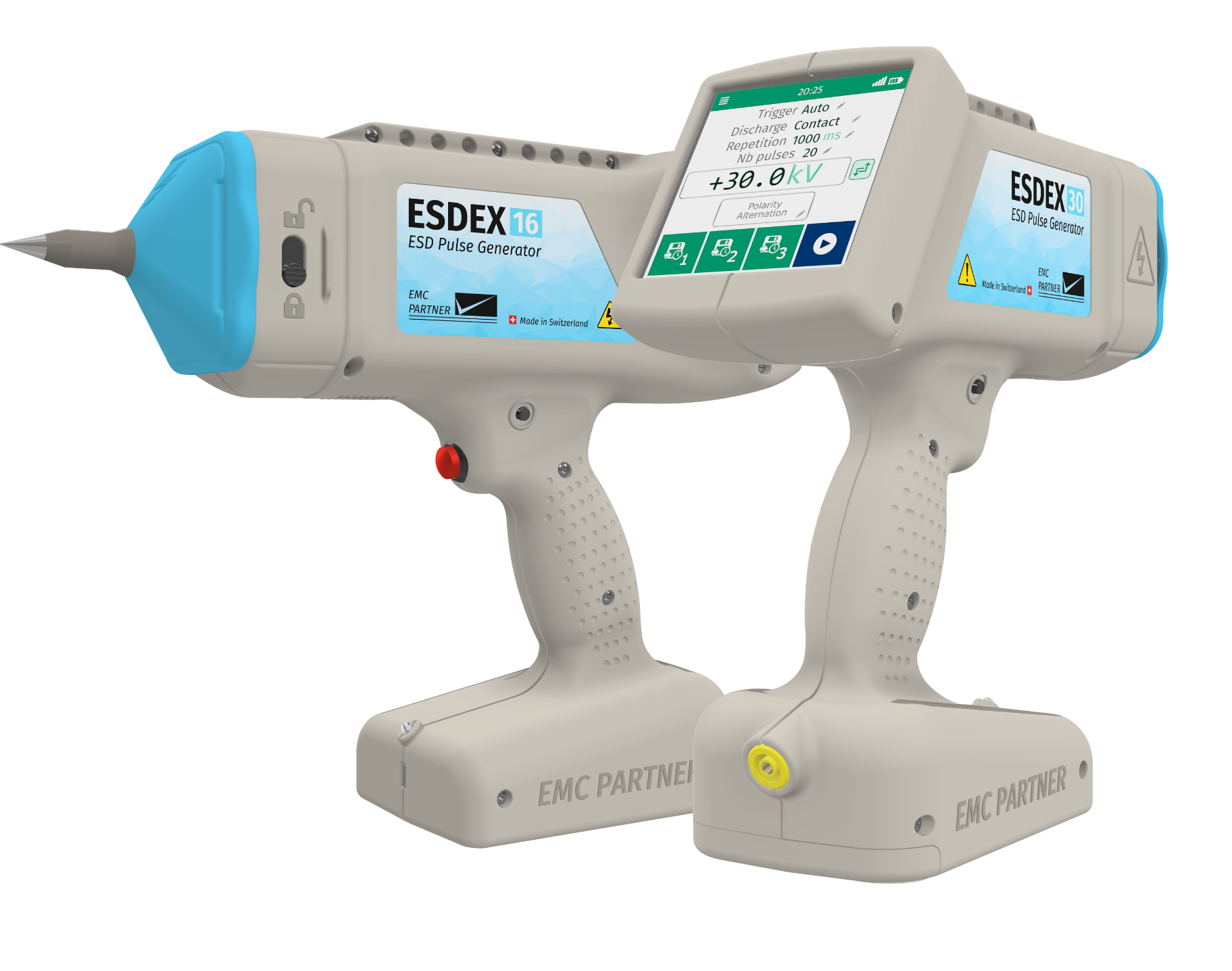
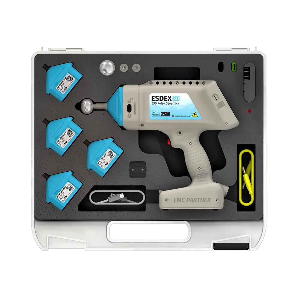
All ESD testing mentioned in IEC 61000-4-2 and this article can be performed with the EMC-Partner ESDEX test system.
Edition 3.0: 2025 of IEC 61000-4-2 cancels and replaces Edition 2.0 from 2008. The technical changes, with respect to the previous edition, are documented as follows.
Added a calibration requirement for ESD generators with an air discharge tip
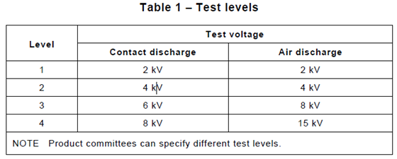
For air discharge, if the contact and air discharge tips consist of a conductor with no additional active or passive electronic components, the calibration can be limited to the measurement of the open circuit voltage at the air discharge tip at the maximum test voltage used for air discharge. Otherwise, it is sufficient to additionally perform the air discharge calibration according to the steps below at one of the levels specified in Table 1 (below) with the ESD generator used in contact discharge mode, but with the air discharge tip mounted.
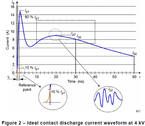
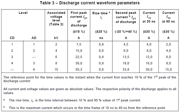
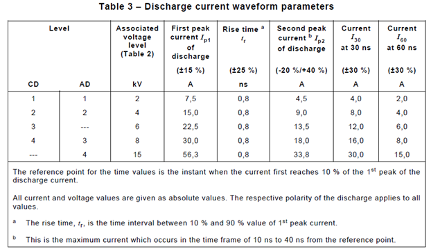
Record the waveform of five discharges for both polarities and measure the following parameters (see Figure 2 and Table 3, below) for each discharge:
Ip1 1st peak value of the discharge current [A]
Ip2 2nd peak value of the discharge current [A]
I30 value of the current 30 ns after the reference point (10 % of Ip1) [A]
I60 value of the current 60 ns after the reference point (10 % of Ip1) [A]
tr rise time of the current [ns]
Verify that each value is within the limits specified in Table 3.
At least one recorded waveform of a contact discharge at 8 kV positive polarity shall be included in the calibration report.
Added a normative annex (Annex I) for test setups for particular kinds of equipment
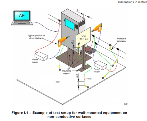
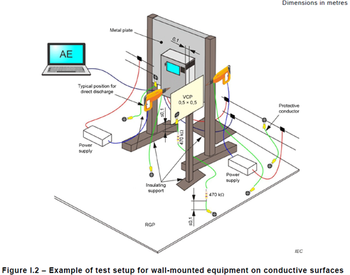
Test Setup for Wall-Mounted Equipment
The test setup shall consist of a non-conductive support (0,8 ± 0,08) m high, standing on the Reference Ground Plane (RGP). The EUT cables shall be isolated from the RGP by an insulating support of (0,5 ± 0,05) mm.
Test Setup for Wearable Devices
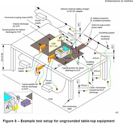
Wearable devices are removable and include body-mounted, body-supported, limb-mounted, and clothing-integrated equipment. These devices shall be tested as tabletop equipment, as shown below.
Added an informative annex (Annex J) for wearable devices
ESD stress on wearable devices differs from the stress on stationary equipment since wearable devices are charged by the human body. Because of different scenarios, such as picking up a wearable device, taking off a wearable device by another person, ESD originating from the human hand of a person wearing device, removing a charged wearable device with one’s own hand and placing the device on a desk, and ESD to other objects directly from the wearable device, there are differences in the current characteristics of the ESD discharge. These differences are limited by impedance and capacitance differences between the listed scenarios.
In order to reproduce the most severe discharge current condition from a wearable device, it is recommended to use an ESD generator with a 200pF storage capacitor and a 50-ohm discharge resistor in series. The recommended method of performing the test is as follows:
-
-
- place the wearable device on the Horizontal Coupling Plane (HCP) as shown in Figure 8 (above)
- use a battery to supply the wearable device. If an external power supply is required, all units should be placed on the HCP
- apply ESD to the conductive parts of the wearable device in contact discharge mode using an ESD generator with a 200 pF storage capacitor and a 50 Ω discharge resistor
- perform the electric charge elimination procedure (per Section 7.3.5, IEC 61000-4-2)
-
Added an informative annex (Annex E) on how to select test points and give guidance on how to specify the number of pulses for direct contact discharges
Guidance for Direct Contact Discharges
Direct contact discharges are generally applicable to metal parts and surfaces of the Equipment Under Test (EUT) using the contact discharge tip of the ESD generator, which are accessible by users or operators. Specifically, contact discharge ESD tests apply to the following:
-
-
- terminals for ESD protection
- ungrounded metal surfaces
- metal shell of coaxial- or multi-pin connectors
- metallic shell of actuators
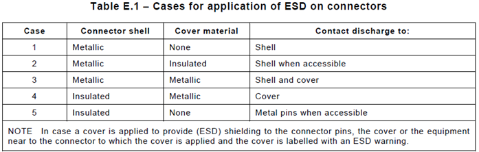
- metallic shell of connectors (see Table E.1, below)
-
Further direct discharges are not necessary on the following:
-
-
- outer metal enclosures of equipment, which are connected to Protective Earth (PE) and where no electronic subassemblies are directly mounted, for example, metal enclosures of AC motors, which are connected to PE
- any parts marked with an ESD warning label
-
Guidance for Air Discharges
Air discharges apply to insulated parts and surfaces of the EUT, using the air discharge tip of the ESD generator, which is accessible to users or operators. Specifically, ESD tests apply to the following:
-
-
- insulated surfaces, including touch screens
- enclosures of class II equipment
- insulated shell of coaxial or multi-pin connectors
- insulated shell of actuators
- non-conductive enclosures of class III equipment (mice, keyboards)
- non-conductive ventilation openings and seams
- areas on insulated enclosures that are nearest to conductive portions of the enclosed circuitry
- other points that are likely to be touched by the human body, such as any surface of a portable product, or by another charged surface, especially near enclosure seams and apertures
-
Further air discharge tests are not necessary on the following:
-
-
- parts marked with an ESD warning label
- parts in such proximity to metal surfaces that the discharge strikes the metal surface, provided that the metal surface is tested with contact discharge.
-
Guidance for Indirect Discharges
Indirect discharges are contact discharges to the Horizontal Coupling Plane (HCP) or Vertical Coupling Plane (VCP). These discharges produce a field that can cause degradation of performance in sensitive electronic equipment. Because ESD is applied to the HCP or VCP via direct discharges by a specified method, this guidance focuses on where to place the VCP relative to the kind of EUT surface to be illuminated, whereas the HCP is always beneath the EUT.
It is unlikely that fields generated by indirect ESD discharges on coupling plates will have any effect on metal surfaces (enclosures) of the EUT, especially when they are connected to PE; i.e., such tests are not appropriate.
Indirect discharge tests are generally performed in the vicinity of non-conductive surfaces (enclosures) of the EUT, as well as for ungrounded equipment, regardless of their surface material.
Investigatory Testing
Investigatory testing can be used in the selection of test points. Discharges with gradually increasing voltage levels should be applied during such testing. This reduces the chances of damaging the EUT and increases the chances of noticing EUT anomalies during testing.
Air discharge investigation on non-conductive EUT parts should be performed first, followed by contact discharge investigation, including HCP and VCP. The purpose of this testing is to indicate susceptible areas of the EUT so that more detailed testing can be performed in those areas. Voltages should be set to a lower level with the air discharge tip oriented perpendicularly to the EUT and tested at various separation distances to identify the candidate test locations. If no upsets or EUT anomalies are noted, the voltage should be gradually increased, and the investigation can continue.
Contact discharge investigation on conductive EUT parts is evaluated similarly to air discharge investigation. Test points selected during investigatory testing should be marked with stick-on labels or arrows added to EUT photographs.
Number of pulses for Direct Contact Discharges
-
-
- EUT with analog circuits: 10 pulses at each polarity, positive and negative
- EUT with digital circuits: 20 pulses at each polarity, positive and negative
-
Moved Clause 9 into a new informative annex (Annex K)
Evaluation of Test Results
Results for ESD testing are based on performance criteria relating to the reduction of function or degradation of the EUT’s performance. The permissible degradation of performance should be specified by the product manufacturer or purchaser. This degradation is relative to a permissible performance specified by product committees. Performance criterion “A” is typically “normal” EUT operation, while criterion “B” allows a permissible degradation of operation so long as the EUT can self-recover to normal operation. Criterion “C” typically allows an interruption of operation that requires an operator to intervene, but no equipment damage is allowed.
Improved current calibration procedure
The following section highlights only changes from 61000-4-2 Edition 2.0 to Edition 3.0. This is not the complete calibration routine.
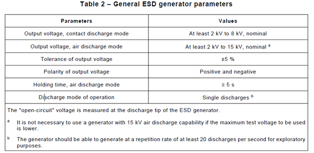
The ESD generator system must be calibrated to ensure the specifications of the tables 2 and 3, below, are met.
ESD generators that can be powered by either mains or battery must have both modes calibrated.
ESD generators shall be calibrated at levels 1-4, in both polarities, as shown in Table 1, below.
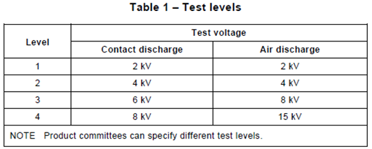
Contact Discharge (CD) calibration shall be performed as follows, with the contact discharge tip mounted. All measured values and a minimum of one discharge current waveform shall be recorded. One recording of the +8.0 kV waveform must be recorded.
Open-Circuit Output Voltage:
Measure the open-circuit voltage of the ESD generator with the discharge switch activated.
Current Waveform:
Complete the following steps and record for each of the 5 discharges for positive and negative polarities.
Ip1 1st peak value of the discharge current [A]
Ip2 2nd peak value of the discharge current [A]
I30 value of the current 30 ns after the reference point (10 % of Ip1) [A]
I60 value of the current 60 ns after the reference point (10 % of Ip1) [A]
tr rise time of the current [ns]
Air Discharge (AD), if the contact and air discharge tips are simple conductors with no additional active/passive components, the calibration can be limited to the open circuit voltage measurement at the air discharge tip. This should be done at the maximum AD test voltage. Otherwise, calibration should be performed at one voltage level with the ESD generator in CD mode, but with the AD tip mounted, as follows.
Current Waveform:
Complete the following steps and record for each of the 5 discharges for positive and negative polarities.
Ip1 1st peak value of the discharge current [A]
Ip2 2nd peak value of the discharge current [A]
I30 value of the current 30 ns after the reference point (10 % of Ip1) [A]
I60 value of the current 60 ns after the reference point (10 % of Ip1) [A]
tr rise time of the current [ns]
Equipment required for ESD generator calibration is as follows.
-
-
- High-voltage meter capable of measuring 15 kV. A resistive high-voltage divider shall be connected for open-circuit output calibration. The accuracy of this divider shall be +/- 1 % with a minimum resistance specified by the maker of the generator.
- Oscilloscope with a >/= bandwidth of 2.0 GHz and sampling rate of >/= 8 GS/s
- Coaxial current target-attenuator-cable chain with calibrated target
- Attenuator
-
The setup for ESD current waveform calibration is as follows.
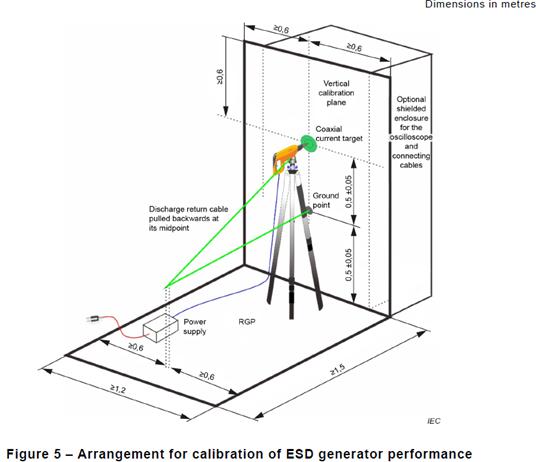
Notes:
-
-
- The generator shall be installed on a non-conductive support
- The RGP and vertical calibration plane shall be electrically connected
- The ESD generator shall make contact with the center conductor of the target
- The discharge return cable shall be pulled backwards at its middle, forming a triangle, and shall not lie on the RGP or be held
- Any ESD generator external power supply shall be placed on the RGP
- No conductive objects shall be placed in the area of the 1.5m x 1.2m calibration setup
- The power cable to the ESD generator shall be routed along the RGP and calibration plane
-
Improved measurement uncertainty considerations with examples of uncertainty budgets
There are many factors, random or systematic, that affect EMC test and calibration results. The comparison of the realized disturbance quantity with the disturbance quantity specified in 61000-4-2 is generally performed via measurement. The result of each measurement includes an amount of measurement uncertainty (MU) from the imperfections of the measuring equipment to the lack of repeatability of the quantity being measured. So, to measure MU, it is necessary to:
-
-
- Identify the sources of uncertainty of the instrumentation and the measurand
- Identify the relationship between the input (influence) and output (measured) quantities
- Assign a probability density function to each of the input quantities
- Calculate the interval containing the possible values of the quantity being measured
-
In immunity tests, intervals are evaluated for the parameters of the disturbance quantity (ie, rise time, peak, duration). These describe the degree of agreement of the disturbance quantity with the relevant specifications of 61000-4-2.
These intervals do not characterize the degree of agreement between the simulated EM phenomenon and the real EM phenomenon in the world outside the test lab.
Since the effect of the parameters of the disturbance quantity on the EUT is not known, a singular interval cannot be assigned to the disturbance quantity. So, each of the parameters of the disturbance quantity is to be accompanied by the corresponding interval. This yields more than one uncertainty budget. Edition 3.0 of IEC 61000-4-2 lists the following example uncertainty budgets for ESD testing.
-
-
- ESD current discharge rise time (tr)
- first peak of the ESD current discharge (Ip1)
- second peak of the ESD current discharge (Ip2)
- ESD current discharge at 30 ns (I30)
- ESD current discharge at 60 ns (I60)
-
Other factors contributing to uncertainty are:
-
-
- Oscilloscope time base error and jitter (typically negligible)
- Oscilloscope vertical resolution (typically negligible)
- Rise time of the step response and bandwidth of the frequency response of the measuring system
- Impulse peak distortion due to the limited bandwidth of the measuring system
-
In order to provide evidence that the generated ESD current discharge is compliant with the requirements of this document, the calibration results can be compared with the tolerances specified by this document. Tolerances cannot be reduced by MU.
Further guidance is provided in IEC/TR 61000-1-6:2012 [7], Clause 6.
Moved post-installation tests into a new informative Annex G since they cannot be performed in a controlled environment
An example of post-installation test setup is shown below. Testing procedures and methods have not changed from Edition 2.0 to Edition 3.0.
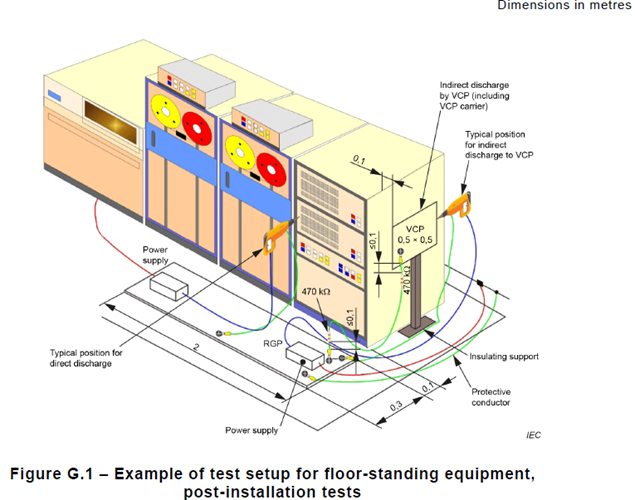
To stay ahead in compliance and testing, it’s essential to adhere to the latest standards. The updates in IEC 61000-4-2 Edition 3.0 consist of new calibration requirements, test setups, and test procedures, which ensure more precise and reliable ESD testing. EMC-Partner’s ESDEX test system is fully equipped to meet these new requirements and provides a top-of-the-line industry solution for your ESD immunity testing needs. Stay compliant and get your equipment tested to the highest standards—contact us today to find out how these updates impact your testing procedures!